Patch Antenna Radiation Pattern
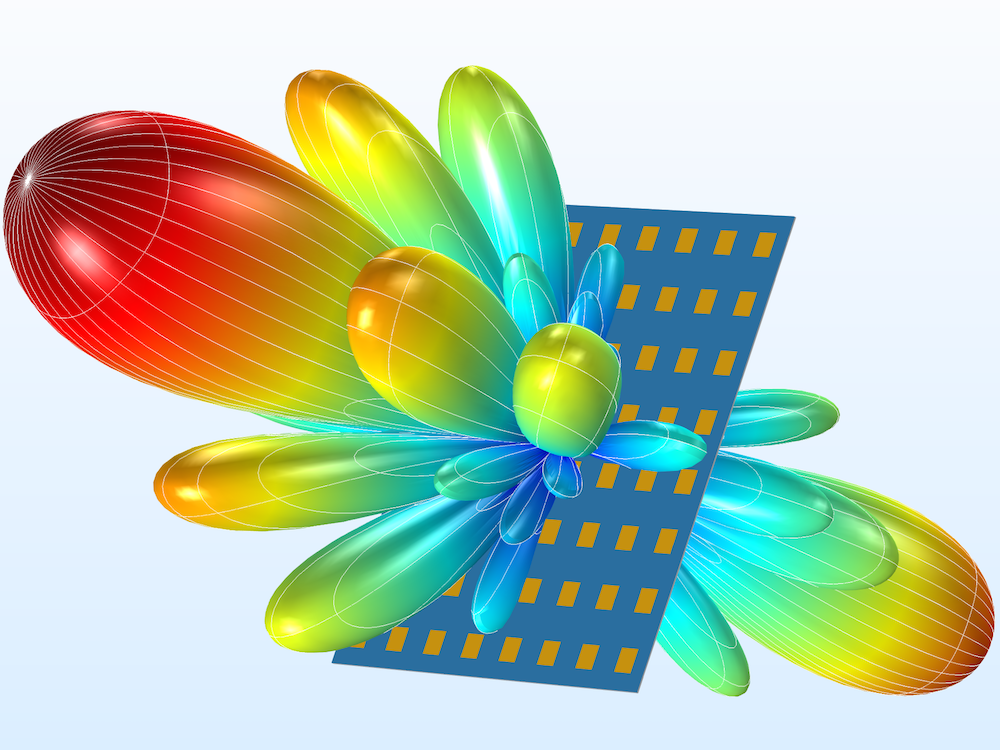
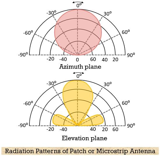
Patch Antenna Radiation Pattern - In a cavity, only certain modes are allowed to exist, at different resonance Design a rectangular patch antenna. The trace of the angular variation of the received/radiated power at a constant radius from the antenna is called the power pattern. The fields are linearly polarized, and in the horizontal direction when viewing the microstrip antenna as in. Radiationpattern 0 10 20 30 40 0 10 20 30 40 0.2 0.4 0.6. The design initially ran through It has low radiation power and narrow frequency bandwidth. The radiation pattern can be shaped by adding directing elements (directors) in front and reflecting elements (reflectors) behind. It demonstrates the usage of open boundary conditions for antennas and farfield monitors with the general purpose frequency domain solvers. Web the patch acts approximately as a resonant cavity (with perfect electric conductor (pec) walls on top and bottom, and perfect magnetic conductor (pmc) walls on the edges). Design a rectangular patch antenna. Web patch antenna consists of a patch of metal on a thin dielectric substrate backed by metal ground, as shown in figure 4. It demonstrates the usage of open boundary conditions for antennas and farfield monitors with the general purpose frequency domain solvers. Microstrip or patch antennas find uses in applications that require low profile antennas without compromising performance. Web the radiation pattern of microstrip or patch antenna is broad. Select frequency around 10ghz, then press ‘compute’. To test, the radiation pattern's recovery capabilities of the ns. To have a greater directivity, an array can be formed by using these patch antennas. And maintains a consistent radiation pattern. Let us look at the pattern of energy radiation. Web an antenna operating in multiband can be designed by creating a staircase pattern in the patch which also results in a 60% reduction in antenna size operating at millimeter wave band. This simple antenna is a suitable. The radiation pattern (rp) (or antenna pattern) is the representation of a radiation property of the antenna as a function of the. The energy radiated by an antenna is represented by the radiation pattern of the antenna. Understand how patch antennas radiate. The figure below represents the radiation pattern of the microstrip antenna: Topics include principles of operation, impedance matching, radiation patterns, circular polarization, bandwidth, efficiency, alternative feed types, stacked patches and higher It demonstrates the usage of open boundary conditions for. The trace of the angular variation of the received/radiated power at a constant radius from the antenna is called the power pattern. Boxed sections that start with the word ”extra” are not required for tests. Λ 0 free space wavelength). The radiation pattern of a microstrip or patch antenna is shown above. The length l represents the distance between two. The design initially ran through This is a 3d plot of the radiated eθ field. Higher gains (up to 10 dbi) can be achieved by using different means including large patch heights and parasitic patches. The resulting radiation pattern is shown in figure 13. Radiation is accounted for by using an effective loss tangent for the substrate. Topics include principles of operation, impedance matching, radiation patterns, circular polarization, bandwidth, efficiency, alternative feed types, stacked patches and higher For this calculation, a substrate height of 50 µ m is chosen. Web an antenna operating in multiband can be designed by creating a staircase pattern in the patch which also results in a 60% reduction in antenna size operating. The radiation pattern can be shaped by adding directing elements (directors) in front and reflecting elements (reflectors) behind. The resulting radiation pattern is shown in figure 13. This power variation as a function of the arrival angle is observed in the antenna's far field. And maintains a consistent radiation pattern. This simple antenna is a suitable. Let us look at the pattern of energy radiation. Web fundamental specifications of patch antennas radiation pattern the patch's radiation at the fringing fields results in a certain far field radiation pattern. Web the patch acts approximately as a resonant cavity (with perfect electric conductor (pec) walls on top and bottom, and perfect magnetic conductor (pmc) walls on the edges).. The figure below represents the radiation pattern of the microstrip antenna: Web a radiation pattern defines the variation of the power radiated by an antenna as a function of the direction away from the antenna. The general idea and necessary steps are indicated. This is a 3d plot of the radiated eθ field. By the end of this lecture, you. This radiation pattern shows that the antenna radiates more power in a certain direction than another direction. Web measuring an antenna's radiation pattern and gain is discussed. Its size reduces by using a multilayer substrate. After waiting, a 3d radiation pattern window will show up. Let us look at the pattern of energy radiation. Select frequency around 10ghz, then press ‘compute’. Web generally, hemispherical coverage is provided by a patch antenna at an angle of 30⁰ to 180⁰ at width from the mount. Let us look at the pattern of energy radiation. This power variation as a function of the arrival angle is observed in the antenna's far field. It has low radiation power. And maintains a consistent radiation pattern. Web a radiation pattern, or antenna pattern is a graphical representation of how a particular antenna radiates or receives energy. Λ 0 free space wavelength). Select frequency around 10ghz, then press ‘compute’. By the end of this lecture, you will be able to: The figure below represents the radiation pattern of the microstrip antenna: Web an antenna operating in multiband can be designed by creating a staircase pattern in the patch which also results in a 60% reduction in antenna size operating at millimeter wave band. Web figure 4 · measured pattern of a patch antenna, with a typical beamwidth of 65º and fairly well suppressed rearward radiation. Web this example shows a rectangular patch antenna. This is a 3d plot of the radiated eθ field. This power variation as a function of the arrival angle is observed in the antenna's far field. The trace of the angular variation of the received/radiated power at a constant radius from the antenna is called the power pattern. Web normalized radiation pattern for microstrip (patch) antenna. Web the radiation pattern of a patch antenna is a function of its width and the shape of its substrate. It demonstrates the usage of open boundary conditions for antennas and farfield monitors with the general purpose frequency domain solvers. The fields are linearly polarized, and in the horizontal direction when viewing the microstrip antenna as in.
How to interpolate E & H field principal cuts to make 3D antenna

Normalised radiation patterns of optimised dual‐band patch antenna

Patch antenna element A, Circular patch geometry; B, path element 3D

Antennas Navipedia
Introduction to Efficiently Modeling Antennas in COMSOL Multiphysics
What is Patch (Microstrip) Antenna? Construction, Working, Radiation

(A) Normalized radiation pattern of turnstile‐shaped patch antenna at

15 Radiation pattern of simple patch antenna at 2.415 GHz integrated

3D radiation patterns of patch antennas with different slot loading at

Antenna's radiation patterns in Eand Hplanes for a monopole antenna
Radiation Patterns Are Diagrammatical Representations Of The Distribution Of Radiated Energy Into Space, As A Function Of Direction.
Let Us Look At The Pattern Of Energy Radiation.
Web Fundamental Specifications Of Patch Antennas Radiation Pattern The Patch's Radiation At The Fringing Fields Results In A Certain Far Field Radiation Pattern.
Web The Radiation Pattern Of Microstrip Or Patch Antenna Is Broad.
Related Post: